Request
HCW1, HCW2, HCW3, HCW4
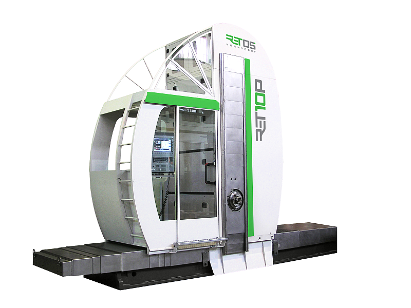
HCW 1- 4 - fully hydrostatic horizontal boring machine, which allows to achieve excellent results during the machining process when removing huge chips, as well as during very precise finishing of the workpiece.
Horizontal milling and boring machine HCW 1 – HCW 4
HCW 1, HCW 2, HCW 3, HCW 4 – fully hydrostatic horizontal boring machine, which allows to achieve excellent results during the machining process when removing huge chips, as well as during very precise finishing of the workpiece.
Operation of the machine
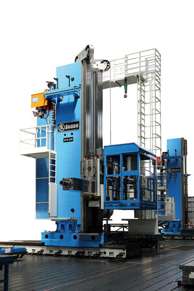
- Main operator’s panel is placed outside the working area on the operator’s platform, where the operator is protected against influences of the machining process (flying chips, broken parts of tools and workpiece, cooling liquid, etc.) by means of cabin with moveable front part.
- With one lockable switch the operator can select following modes of machine’s operation
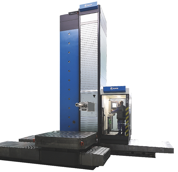
Description of basic version
- Bed grey cast iron structure
- Four guideways
- Upper and lateral guideways hydrostatic
- Hardeness of guideways (hydrostatic) 200 ± 20 HB
- Hardened and ground rack for column travel
- Saddle of column grey cast iron structure
- Low – friction special plastic material attached to the hydrostatic guide ways
- Hydraulically controlled clamping units in the edge of column saddle
- Backlash-free movement of the saddle via double preloaded pinion driven by “Master-Slave” system
- Limit switches for column travel
- Column grey cast iron structure
- Guiding of headstock along column is hydrostatic, rear guideways is rolling
- Ball screw with rotating nut for movement of headstock along column
- Counterweight inside the column
- Limit switches for headstock travel
- Ladder for entrance on operator´s platform
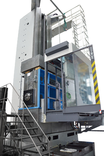
- Headstock
- Extensible boring spindle with unextensible milling spindle mounted co-axially in the extensible square ram.
- Hydrostatic guiding of ram in headstock.
- Nitrided work spindle and milling spindle.
- Seating of spindle in a special ball bearing with oil lubriction.
- Ball screws for spindle, ram and headstock out-travel.
- Three-step spindle drive with gears in continuous mesh and hydraulically shifted claw clutches.
- Thermal stabilization of headstock oil fillings.
- Oriented spindle stop and sensing of spindle position by means of rotary encoder
- Mechanised tool collet clamping (hydraulically operated tool release, tool clamping by disk springs).
- Mechanised clamping of milling and boring heads onto the ram face through a central clamping units which is a part of accessories and it is controlled from the machine panel.
- Disk brake for main drive emergency spindle stop.
- Automatic lubrication of all functions.
- Supply of energies for technological accessories inside the ram.

HCW1, HCW2, HCW3, HCW4
HCW 2000, HCW 3000, HCW 4000
FCW 140, FCW 150, FCW 160
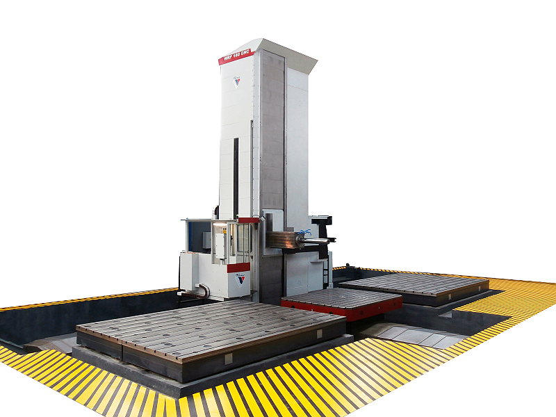
WRF 160 CNC / WRF 160 HEAVY
WRF150 CNC
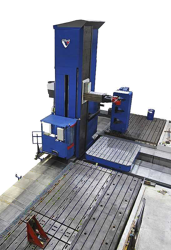
WRF 130 CNC
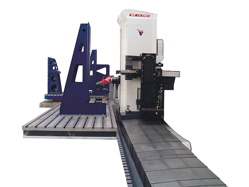
WF 13 CNC
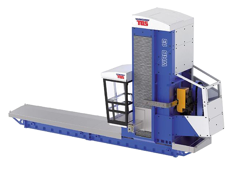
WRD 13 (Q)
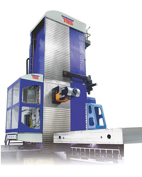
WRD 130 / WRD 150 (Q)
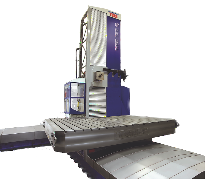
WRD 170 (Q)
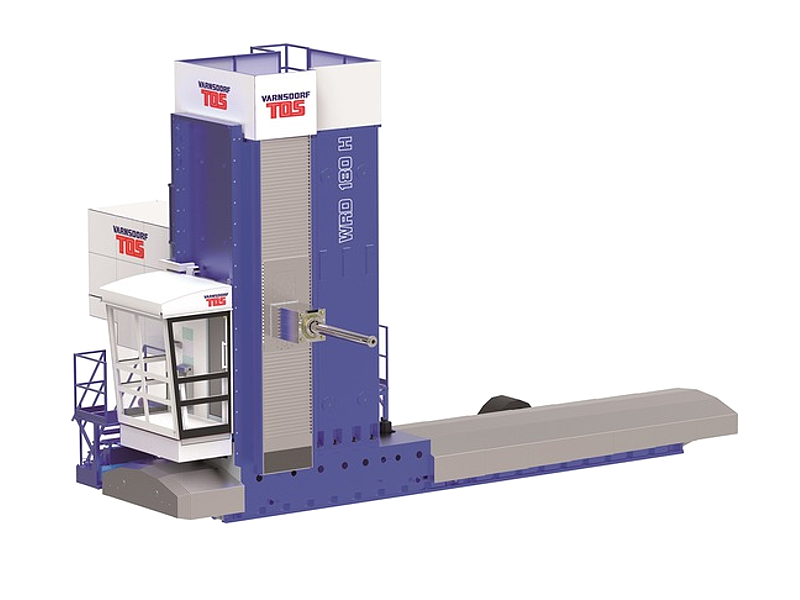
WRD 180 H