Archives

CNC LATHE with driven tools

KL285

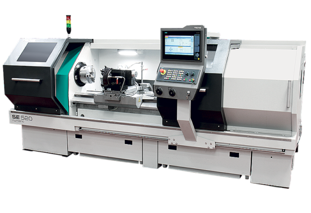
KL285 Turning Center

Machine overview

KL285 is a modern CNC turning center of the KL series manufactured by KOVOSVIT MAS. The designation KL originates from Kovosvit Lathe, while the number 285 refers to the typical machined diameter of the workpieces. The machine represents a significantly redesigned and innovative construction and gradually replaced the earlier SP280 machine series in production.

KL285 was developed with a focus on high precision, stability, operator comfort and energy efficiency. It is suitable for universal turning as well as demanding applications in piece production, small‑batch manufacturing and specialized production.


Machine construction and machining accuracy

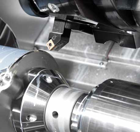
The KL285 turning center is well known for its high machining accuracy. During testing of the most precise Super Precision version, accuracy levels were achieved that allow turning operations to approach grinding quality. In selected technological processes, grinding can therefore be partially or completely eliminated.

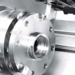
This high level of accuracy is achieved, among other factors, by mounting the headstock on a massive polymer concrete console, which provides:

  • effective vibration damping,
  • reduced heat transfer,
  • significantly improved thermal stability of the machine.

These properties directly contribute to excellent surface quality and long‑term machining accuracy.


KL285 QUICK version – cast‑iron bed

The newly introduced KL285 QUICK version is built entirely on a cast‑iron bed, a traditional and proven machine tool material. Cast iron ensures sufficient rigidity and, consequently, reliable machining accuracy for standard turning operations.

In the QUICK version, the machine is equipped with a standard Sauter turret, unlike the more precise turret used in the Super Precision variant. Despite these differences, the QUICK version provides all the qualities required for standard industrial turning. Thanks to more than 80 years of KOVOSVIT MAS experience in turning technology, KL285 QUICK satisfies the needs of the vast majority of end users, while the Super Precision version remains available for the most demanding applications.


Significant improvement compared to SP280

The KL285 turning center fully replaced the older SP280 machine series, which had been developed more than ten years earlier. Compared to SP280, KL285 introduces substantial improvements, particularly in:

  • accessibility of the working area,
  • ergonomics and operator comfort,
  • machine transparency and visibility.

The distance from the door to the spindle axis is only 350 mm, making workpiece handling considerably easier. A large safety‑glass window further enhances visibility inside the working area.

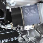
The machine is also energy‑optimized, featuring:

  • drive energy recuperation,
  • frequency converters for various machine components,
  • optional compressed air saving by switching off sealing air during non‑productive times.

Operator control, comfort and positioning accuracy

During development, strong emphasis was placed on simplicity, user friendliness and operator comfort. All machine settings are adjusted directly via the control panel using the CNC system’s user screens.

From the screen, operators can:

  • set clamping pressures,
  • control movements and positioning,
  • perform setup tasks without mechanical adjustments previously required during workpiece changes.

Positioning accuracy is further improved by the use of direct drives for ball screws, with motors connected directly to the ball screws without intermediate gearing. Additionally, a reduced ball screw pitch increases positioning precision.

A new 15″ touchscreen control panel, which is both swiveling and tilting, significantly improves comfort, especially for operators programming directly at the machine.


Technological capabilities and configurations

The KL285 turning center was available in several configurations, such as:

  • MC
  • Y
  • SMC
  • SY

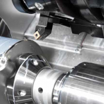
The Super Precision variant offers:

  • a tailstock,
  • driven tools,
  • Y‑axis,
  • temperature stabilization.

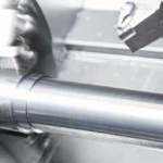
KL285 is suitable for economical and universal machining of flanges, shafts and bar material. The modular system and wide range of accessories allow both simple turning with a single support and multi‑axis turning, including milling operations outside the turning axis using the Y‑axis.


Typical applications of KL285

KL285 is commonly used for:

  • universal turning operations,
  • machining of shafts and flanges,
  • turning with driven tools,
  • drilling and milling using the Y‑axis,
  • piece production, small‑batch and specialized manufacturing.

Thanks to its rigidity, stability and accuracy, the machine is also suitable for producing highly precise workpieces.


Machine working environment

The KL285 is designed to operate in a standard workshop environment without exposure to aggressive fumes or conductive dust.

Recommended operating conditions:

  • ambient temperature: +15 °C to +35 °C,
  • maximum relative humidity: 80 %,
  • maximum absolute humidity: 15 g/m³,
  • specified accuracy achieved at 20 ± 3 °C.

Service and spare parts for KL285

Although production of the KL285 has been discontinued, many machines remain in active industrial use. Therefore, we provide:

  • aftermarket service for KL285 turning centers,
  • supply of spare parts (mechanical, electrical and control components),
  • machine diagnostics and repairs,
  • technical consulting for operation and maintenance,
  • support focused on extending machine service life.

If you operate a KL285 turning center, we are ready to provide professional service support.

CNC LATHE with driven tools

CNC LATHE with driven tools

KL435

KL435 Turning Center

Machine overview

KL435 is a CNC turning center of the KL series manufactured by KOVOSVIT MAS, designed for universal and productive turning of medium‑size and larger rotational workpieces. The designation KL stands for Kovosvit Lathe, while 435 refers to the typical machined diameter within this machine class.

The KL435 represents a modern lathe design based on KOVOSVIT MAS’s long‑term experience in turning technology. It is suitable for piece production, small‑batch manufacturing and specialized applications where rigidity, accuracy and long‑term stability are required.


Machine structure and rigidity

The KL435 turning center is designed with a strong emphasis on mechanical rigidity and long‑term geometric stability. Its robust machine structure provides:

  • stable cutting conditions during heavy turning operations
  • effective vibration damping
  • consistent accuracy even under long machining cycles

Thanks to the solid construction concept, the KL435 delivers reliable results in terms of dimensional accuracy and surface quality.


Accuracy and machining performance

KL435 is designed to meet demanding requirements for precise turning of rotational components, such as shafts, flanges and geometrically complex parts. The machine performs reliably during both roughing and finishing operations.

The use of modern drive systems, high‑quality axis guidance and optimized machine design positively affects:

  • positioning accuracy
  • repeatability of machining
  • quality of the final surface

Operator comfort and ergonomics

During the development of the KL435, attention was also paid to operator comfort and ergonomic design. The layout of the machine ensures:

  • good access to the working area
  • clear visibility during setup and operation
  • safe and user‑friendly handling

The ergonomic concept simplifies daily operation, setup and maintenance, which directly supports higher productivity and safer operation.


Technological capabilities and configurations

The KL435 turning center was available in several configurations, allowing adaptation to different production needs. Depending on the version, the machine could be used for:

  • standard turning operations
  • machining of complex rotational shapes
  • shaft and flange production
  • precision turning with high stability requirements

The modular design enables deployment across a wide range of industrial applications.


Typical applications of KL435

KL435 is commonly used for:

  • universal turning operations
  • machining of medium‑size and larger rotational parts
  • piece and small‑batch production
  • precision turning with long machining cycles

Thanks to its rigid design and stable machining behavior, the machine is also suitable for continuous production use.


Production period

The KL435 turning center was manufactured approximately during the second decade of the 21st century as part of the KOVOSVIT MAS product portfolio. Many machines remain in active industrial operation today.


Service and spare parts for KL435

Although production of the KL435 has been discontinued, a significant number of machines are still in daily use. We therefore provide:

  • aftermarket service for KL435 turning centers
  • supply of spare parts (mechanical, electrical and control components)
  • diagnostics and repairs
  • technical consulting for maintenance and operation
  • support aimed at extending machine service life

If you operate a KL435 turning center, we are ready to provide professional service support.

CNC LATHE with driven tools

Vertical console milling machine

FGV32

Vertical console milling machine FGV32

The FGV32 vertical console milling machine is intended for a broad range of milling, drilling, and boring operations on small to medium-sized workpieces, in all areas of machine manufacture, up to a maximum workpiece weight of 250 kg. The machine can be equipped with special accessories that expand its technological and operational use. A suitable selected range of spindle speeds and wide range of working feed rates make these machine suitable for machining all kinds of materials.

VERTICAL KNEE‑TYPE MILLING MACHINE

Design and technical data of the basic machine as per technical specification

  • in metric version
  • with vertically arranged traveling spindle
  • electrical equipment designed for 3x 400V/50cyc
  • including standard equipment

Advantages:

  • hight rigdity of the machine frame and driving mechanism
  • annealed guide surfaces
  • automatic cycle in the X-axis with console lowering (for an extra charge)
  • consecutive milling
  • gauges in the longitudinal and transverse axis
  • central lubrication system (manualy operated)
  • simple machine control, primarily from the operator’s position
  • smooth movement setting in all axes
  • well proven design, precision workmansip of all components
  • drive mechanism on the right side of the logitudinal table for the rotary table, universal dividing attachment
  • climb milling attachments
  • push-button panel for easy check of the machine operation
  • tool cooling system, capacity 42 l/min.

Standard accessories

  • Lighting
  • Cooling equipment
  • Milling arbor, short ISO 50x32x60
  • Instructions for attendance and maintenance with lubricant table – 2 pcs
  • Accuracy chart
  • Standard color – pale grey/blue

Other machine configurations

The machine can also be ordered in a different configuration, which however must be specified in the order. This is subject to additional charges, and the delivery date is subject to mutual agreement.

  • electrical equipment for values other than 3 x 380V / 50 Hz,
  • Imperial system version (inches)
  • numerical position indication
  • higher spindle RPM range (45 – 2000)
  • different colour or shade surface finish

The manufacturer reserves the right to change the product parameters and design without prior notice.

The universal milling machine

FGU32

The universal milling machine FGU32

FGU32 – The universal milling machine is designed for a wide range of milling operations, on components of medium size, both in one off and long run production. A suitable selected range of spindle speeds and wide range of working feed rates make these machine suitable for machining all kinds of materials.

Basic machine features

  • high rigidity of the machine frame and driving mechanisms
  • versatility of the milling machine
  • well‑proven design, precision workmanship of all components
  • climb milling attachment
  • push‑button panel for easy check of the machine operation
  • central lubrication system (manually operated)
  • work table can be swivelled about its vertical axis by 45E in either direction
  • automatic feeds X,Y,Z (stepless)
  • tool cooling system, capacity 42 l/min
  • overarm with bearing (horizontal)
  • hardened guideways in Y, Z axes
  • standard color: blue/pale grey

Design and technical data of the basic machine as per technical specification

  • in metric version
  • with horizontally arranged spindle, overarm with two long milling arbor supports
  • electrical equipment designed for 3 x 400/50 cycles
  • including standard equipment

Optional extras

  • Automatic trip-controlled cycles in longitudinal axis (X)
  • Knee and table retraction 0,5 mm
  • Pneumatic tool clamping (in the main spindle of the machine)
  • Vertical milling head IFV 20
  • Universal milling head IFU 20
  • Arbors for IFU 20 :
    • ISO 40x22x140/C56
    • ISO 40x27x140/C56
    • ISO 40x32x140/C56
    • ISO 40x40x140/C56
  • All-angle universal milling head IFP 32
  • Swinging-away arm IOR 20 for IFV20, IFU20, IOF20 (cannot be used for IFP32)
  • Slotting head IOF 20
  • Milling arbor, long:
    • ISO 50x22x500/D40
    • ISO 50x27x630/D40
    • ISO 50x32x630/D40
    • ISO 50x40x630/D40
  • Universal dividing head DU 250 A
  • Vertically adjustable tailstock VK 250 A
  • Cross plate KD 250 A
  • Gear quadrant ZL 250 A
  • Support PA 250 A
  • Hand operated rotary table with dividing attachment dia. 320 mm
  • Clamp No. 411 090577 for hand operated rotary table
  • Machine vice with moving jaw 125 mm
  • Swivelling machine vice 125 mm
  • Swivelling and tilting machine vice 125 mm
  • Self-centering vice 125 mm
  • And more (on request)…
Vertical Knee-type Milling Machine

F2V/R

Vertical Knee-type Milling Machine F2V/R

Vertical knee-type milling machine F2V/R is designed for milling and drilling operations of small and medium-size components of up to 200 kg weight occurring in all branches of the engineering production. Milling head with the spindle seated in the slide sleeve can be inclined in the longitudinal plane of the table. The wide range of speed and feeds enables effective milling of all metals with tools made from a high speed steel or a hardmetal.

Using of the optional equipment from our variety entlarges technological possibilities of the machine.

Advantages:

  • Modern styling and consummate surface finish through oil-resistant varnishes
  • Possibility of horizontal machining – swivelling of spindle by 90°
  • High torque on spindle
  • Continuous set-up feeds in 3 axes by means of a frequency convertor
  • Stepless regulation of spindle revolutions by frequency convertor in two revolution ranges
  • Large working stroke of the quill
  • Rough, fine and maschine shift-out of the spindle quill
  • Spindle in shifting quill efficient for comfortable drilling
  • Simple operation
  • Central lubrication system
  • Compact maschine design

Standard accessories / execution:

  • Table size 300 x 1300 mm
  • Clamping bolt for tools and milling arbors
  • Short milling arbor ISO40x22x37
  • Frequency convertor in spindle drive
  • Maschine shift-out of the quill
  • Automatic feeds X,Y,Z (stepless) – in one step
  • Handwheels in axes X,Y with measuring dials – dividing 0,05 mm
  • Handwheel in axis Z with measuring dial – dividing 0,02 mm
  • Electrical equipment for 400V/50 cycles
  • Paint of machine – blue/grey RAL 5010/RAL 9002

Optional accessories:

  • Horizontal head IFH2
  • Slotting head HOB2
  • Universal dividing attachment 200
  • Its accessories – special price list available –
  • Rotary table – manual dia. 250
  • Machine vices – fixed, rotary, tilting, self-centering
  • Milling arbors – short
  • Reduction sleeves
  • Clamping bush ISO 40×70
  • Collets (various – or in one set of 24 pcs)

Special execution (must be required in the order):

  • Inch execution
  • Other electrical standards than 400V/50 cycles
  • Paint in other coloured shade
  • Pneumatic clamping of tool
  • Machine equipped with digital read-out
  • Stepless feeds in two steps through frequency convertor, two steps gear box
  • Digital position indication for 3 axis

The manufacturer (TOS) reserves the right to change the product parameters and design without prior notice.

CNC vertical machining centres MC1040V

MC1040V

MCV 1040V service

MCV 1040V service is provided for this vertical CNC machining center originally manufactured by TOS / TRENS Trenčín. The MCV 1040V belongs to a traditional and well‑proven series of machining centers designed for universal three‑axis machining of flat and box‑type components. Over many years of operation, this machine type has proven itself in both single‑piece and serial production across a wide range of industrial sectors.

Although production of the MCV 1040V has been discontinued and new machines are no longer available, this does not mean the end of its operational potential. With proper maintenance, professional service and targeted modernization, the MCV 1040V continues to hold a full‑value place in modern manufacturing environments.


Characteristics of the MCV 1040V Machine

The MCV 1040V is a vertical CNC machining center designed for milling, drilling, boring, reaming and thread cutting operations. Its construction allows machining of external and internal planar surfaces, as well as contoured, spherical and geometrically complex shapes.

The machine is equipped with digital servo drives and can be fitted with direct axis measurement using linear scales, ensuring high positioning accuracy and excellent repeatability even during long‑term operation.

Thanks to its robust mechanical design, optimized axis layout and wide configuration options, the MCV 1040V remains capable of stable and reliable machining performance even after many years of use.


Machine Design and Technical Capabilities

The MCV 1040V machining center was produced in versions with either sliding guideways or linear rolling guideways:

  • Sliding guideways offer high rigidity and excellent vibration damping and are especially suitable for heavier and force‑intensive machining operations.
  • Linear rolling guideways are intended for applications requiring higher dynamics, fast feed rates and positioning speeds while maintaining overall machine rigidity.

Spindle drive solutions include:

  • two‑speed automatic gearbox,
  • belt‑driven spindle,
  • direct spindle drive (depending on machine configuration).

Precise axis positioning is ensured by servo drives combined with hardened and ground ball screws manufactured to accuracy class 3.


Control Systems and Tool Magazines

The MCV 1040V machining centers were supplied with various CNC control systems, most commonly:

  • Heidenhain
  • Siemens
  • Fanuc
  • Mitsubishi
  • Fagor

Depending on configuration, the machine could be equipped with:

  • a horizontal tool magazine with a capacity of 20 tools, or
  • a vertical tool magazine with a swing‑arm changer offering 24 to 40 tool positions.

The ISO 40 spindle taper allows the use of a wide range of standard cutting tools.


Service and Spare Parts for MCV 1040V

Even though the MCV 1040V machining center is no longer in production, we are able to support its continued operation according to its technical condition and spare part availability:

  • professional service of mechanical, electrical and CNC components,
  • supply of spare parts (original and alternative solutions),
  • repair and overhaul of spindles, gearboxes, drives and guideways,
  • service and refurbishment of measuring systems,
  • diagnostics and troubleshooting,
  • preventive inspections and technical machine audits.

If specific original components are no longer available, we propose technical replacement solutions that preserve machine functionality, safety and operational reliability.


Modernization and Retrofit Solutions

For MCV 1040V machines, we also offer partial or complete retrofit solutions that can significantly extend machine service life:

  • CNC control system modernization or replacement,
  • replacement of drives and electrical components,
  • renewal of electrical cabinets,
  • increased operational reliability and safety,
  • improved machine ergonomics and user interface.

Key Advantages of the MCV 1040V

  • massive structure made of grey cast‑iron castings
  • stable geometry and long‑term machining accuracy
  • option of direct axis measurement using linear scales
  • universal application in single‑piece and serial production
  • wide possibilities for service, repair and modernization
  • technical support available even after discontinuation of production
SE 520 SL service

SE 520 SL

SE 520 SL service

SE 520 SL service is provided for the CNC universal center lathe originally manufactured by TOS / TRENS Trenčín, based on the SE 520 design but extended with a longer bed up to 2000 mm between centers and a fully enclosed working area. The SE 520 SL NUMERIC is designed primarily for efficient machining of long rotational components with high demands on accuracy, safety and productivity.

Although production of the SE 520 SL NUMERIC has been discontinued, we continue to provide complete service, spare parts supply, technical support and modernization options to ensure reliable long‑term operation.


Characteristics of the SE 520 SL NUMERIC Lathe

The SE 520 SL NUMERIC belongs to the category of CNC universal center lathes and is particularly suitable for machining long shaft‑type and flange‑type workpieces made of metal and plastic materials. Thanks to its extended bed and fully enclosed working area, it significantly expands technological capabilities compared to the standard SE 520 version.

The machine can be supplied in various special configurations and equipped with a wide range of accessories to meet specific technological requirements.


Manual and Automatic CNC Operation

The SE 520 SL NUMERIC allows operation in two modes:

  • manual turning using electronic handwheels,
  • automatic CNC operation via a modern control system.

This combination is especially advantageous in single‑piece and small‑batch production, allowing fast response to changing orders while simultaneously increasing productivity.


Machine Design and Machining Accuracy

The SE 520 SL NUMERIC is designed with a strong emphasis on long service life and stable machining accuracy:

  • key machine components are stress‑relieved by annealing,
  • belt‑driven spindle transmission minimizes vibration during machining,
  • automatic gear shifting within CNC cycles improves production efficiency,
  • bearings with lifetime grease lubrication reduce operating costs.

The overall machine design ensures high accuracy and long‑term stability throughout the entire service life.


Safety, Enclosure and Productivity

A major feature of the SE 520 SL NUMERIC is its fully enclosed working area, which:

  • protects the operator from flying chips,
  • prevents coolant leakage,
  • enables the use of higher coolant pressures and higher cutting speeds.

This significantly increases productivity while maintaining maximum operator safety. The machine is equipped with automatic door locking and impact‑resistant safety glass as standard.


Equipment, Ergonomics and Configuration Flexibility

The SE 520 SL NUMERIC offers a highly comfortable working environment, including:

  • movable control panel with a 15″ Siemens touch screen,
  • intuitive and user‑friendly software interface,
  • LED workspace lighting,
  • centralized automatic lubrication system.

Extensive configuration options include:

  • hydraulic workpiece clamping,
  • hydraulically operated tailstock,
  • hydraulically or manually operated self‑centering steadies,
  • mounting block for anti‑vibration boring bars,
  • driven tools,
  • wide range of clamping plates.

SE 520 SL Service and Spare Parts

Even though the SE 520 SL NUMERIC is no longer in production, we provide comprehensive SE 520 SL service, including:

  • service of mechanical, electrical and CNC components,
  • supply of SE 520 SL spare parts,
  • spindle, gearbox and drive repairs and adjustments,
  • CNC control system and operator panel service,
  • fault diagnostics and technical audits,
  • preventive and scheduled maintenance.

If original components are no longer available, we propose technically equivalent replacement solutions with a strong focus on safety, accuracy and machine lifetime.


Modernization and Retrofit – SE 520 SL Service

As part of SE 520 SL service, we also offer modernization solutions:

  • CNC control system upgrade or replacement,
  • modernization of electrical installations and control cabinets,
  • increased machine safety standards,
  • improved operator ergonomics and renewal of control elements,
  • extension of overall machine service life.

Key Advantages of the SE 520 SL NUMERIC

  • CNC universal center lathe for long workpieces
  • extended bed up to 2000 mm between centers
  • fully enclosed working area
  • manual and automatic CNC operating modes
  • wide configuration and accessory options
  • service and technical support available after end of production
CNC heavy lathes

SR1, SR2, SR3, SR4, SR5

CNC heavy lathes series SR

SR 1, SR 2, SR 3, SR 4, SR 5 – a series of universal horizontal CNC heavy lathes with a maximum diameter above the bed of 6 meters, a workpiece length of up to 30 meters and a maximum workpiece weight of 350 tons. The well-thought-out modular design of the machine allows you to optimize the configuration to meet customer requirements. The supporting parts of the machine are made of stable and solid gray cast iron. The machine can be equipped with accessories for milling, deep drilling and grinding operations. The range of heavy horizontal center lathes TYPES SR1 to SR5 with a modern design is designed for efficient and precise machining of rotating parts and represents a combination of maximum stability, high accuracy and cutting force.

Description:

  • The machine is provided with the common bed with four (4) guide ways.
  • The bed that is made from grey cast iron (GG25).
  • Two guide ways for guiding the carriage (further carriage guiding).
  • Two guide ways for guiding the tailstock and the steady rests (further workpiece guiding).
  • The upper surfaces of the guide ways are in identical plane.
  • Four ways design allows carriage passing over the headstock, tailstock and steady rests.
  • The bed is joined with the foundation through anchoring bolts that enable additional levelling of the bed both in the horizontal and vertical directions.

Carriage guiding

  • The flat guide ways, hardness of which is 200 HB ± 10%, are designed for hydrostatic guiding of the carriage.
  • The guide ways are covered with waterproof telescopic covers placed over the whole width of the carriage guiding.
  • The rack for the saddle feed mechanism is placed between guide ways.
  • The measuring scale for Z-axis as well as the stops for end positions of the carriage are situated in the same space.
  • In the bed casting there are the cross chutes for ease draining of hot oil from the hydrostatic guiding system to the channels located on the sides of the bed. This arrangement decreases thermal deflections of the bed.
  • The suspended pins are permanently mounted at the sides of the bed.
Horizontal milling and boring machine

HCW1, HCW2, HCW3, HCW4

Horizontal milling and boring machine HCW 1 – HCW 4

HCW 1, HCW 2, HCW 3, HCW 4 – fully hydrostatic horizontal boring machine, which allows to achieve excellent results during the machining process when removing huge chips, as well as during very precise finishing of the workpiece.

Operation of the machine

  • Main operator’s panel is placed outside the working area on the operator’s platform, where the operator is protected against influences of the machining process (flying chips, broken parts of tools and workpiece, cooling liquid, etc.) by means of cabin with moveable front part.
  • With one lockable switch the operator can select following modes of machine’s operation

Description of basic version

  • Bed grey cast iron structure
    • Four guideways
    • Upper and lateral guideways hydrostatic
    • Hardeness of guideways (hydrostatic) 200 ± 20 HB
    • Hardened and ground rack for column travel
  • Saddle of column grey cast iron structure
    • Low – friction special plastic material attached to the hydrostatic guide ways
    • Hydraulically controlled clamping units in the edge of column saddle
    • Backlash-free movement of the saddle via double preloaded pinion driven by “Master-Slave”  system
    • Limit switches for column travel
  • Column grey cast iron structure
    • Guiding of headstock along column is hydrostatic, rear guideways is rolling
    • Ball screw with rotating nut for movement of headstock along column
    • Counterweight inside the column
    • Limit switches for headstock travel
    • Ladder for entrance on operator´s platform
  • Headstock
    • Extensible boring spindle with unextensible milling spindle mounted co-axially in the extensible square ram.
    • Hydrostatic guiding of ram in headstock.
    • Nitrided work spindle and milling spindle.
    • Seating of spindle in a special ball bearing with oil lubriction.
    • Ball screws for spindle, ram and headstock out-travel.
    • Three-step spindle drive with gears in continuous mesh and hydraulically shifted claw clutches.
    • Thermal stabilization of headstock oil fillings.
    • Oriented spindle stop and sensing of spindle position by means of rotary encoder
    • Mechanised tool collet clamping (hydraulically operated tool release, tool clamping by disk springs).
    • Mechanised clamping of milling and boring heads onto the ram face through a central clamping units which is a part of accessories and it is controlled from the machine panel.
    • Disk brake for main drive emergency spindle stop.
    • Automatic lubrication of all functions.
    • Supply of energies for technological accessories inside the ram.
Horizontal milling and boring machine

HCW 2000, HCW 3000, HCW 4000

Horizontal milling and boring machine HCW 2000 – 4000

HCW 2000, HCW 3000, HCW 4000 – horizontal milling and boring machines, fully hydrostatic high-speed machine achieving micron accuracy even when the quill is fully extended from the headstock. The stability of the boring machine is ensured by a rigid frame cast from gray cast iron. The pull-out quill is hydrostatically guided with automatic compensation of the drop during extension. The spindle is mounted in special angular contact ball bearings. The spindle is mounted in special angular contact ball bearings and lubricated with a minimum amount of oil. Shifting is provided by hydraulics via gear couplings. A large number of special and additional accessories can be supplied with the machine.

Description of main groups of machine:

Bed

  • Grey cast iron structure – GG 30 (DIN)
  • Two main guide ways and two side guide ways
  • Upper (main) and side guide ways hydrostatic. Side guiding on inner surfaces of the bed.
  • Grounded or fine milled surface of guide ways
  • Hardness of guide ways for hydrostatic 200 +/- 20 HB
  • HEIDENHAIN linear scale for X-axis located on the bed
  • Hardened teeth rack for X – axis feed bolted to the bed section
  • Limit switches for X – axis
  • Telescopic protective steel-sheet covers over the whole width of the bed with slope towards chip conveyor

Column Saddle

  • Grey cast iron structure – GG 25 (DIN)
  • Moving along the bed (X axis)
  • Low-friction special plastic material attached to the hydrostatic guide ways of saddle
  • Hydrostatic oil is supplied to guide ways by high pressure coming through hydrostatic pockets; hydrostatic oil pressure is controlled by CNC system
  • Thickness of hydrostatic oil film about 0,02 – 0,03 mm
  • Backlash-free twin-pinion gearbox driven by two AC drive in Master-Slave loop for movement in X – axis

Column

  • Grey cast iron structure – GG 30 (DIN)
  • Firmly attached to column saddle by set of bolts
  • Double-wall front side of casting
  • Upper (main) and side guide ways hydrostatic. Side guiding on inner surfaces of the column.
  • Rear guiding hydrostatic.
  • Grounded or fine milled surface of guide ways
  • Counterweight for ram’s dropping compensation inside the column
  • HEIDENHAIN linear scale for Y-axis located on the column
  • Ball screw with rotating nut for movement in Y – axis (K100x20)
  • Limit switches for Y – axis
  • Telescopic protective steel-sheet covers over and below the headstock
  • Ladder for entrance to platform of headstock or column’s top