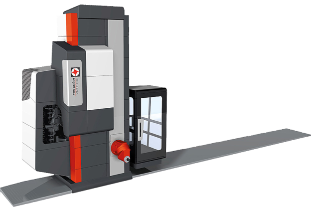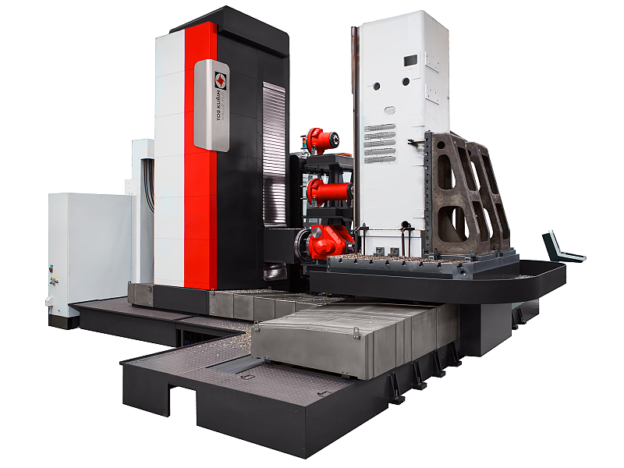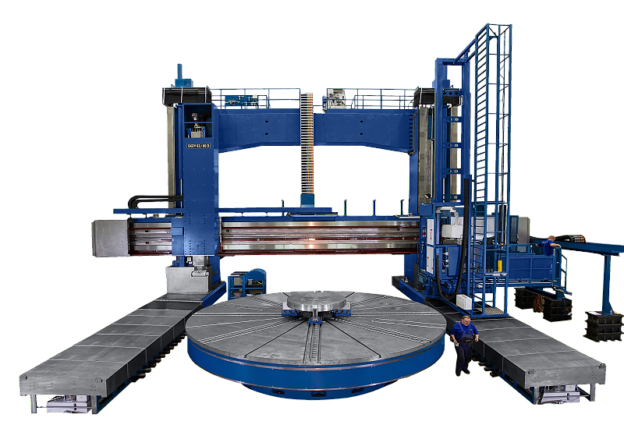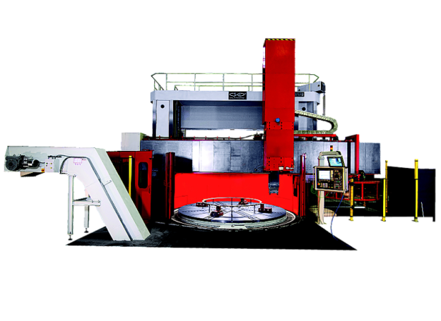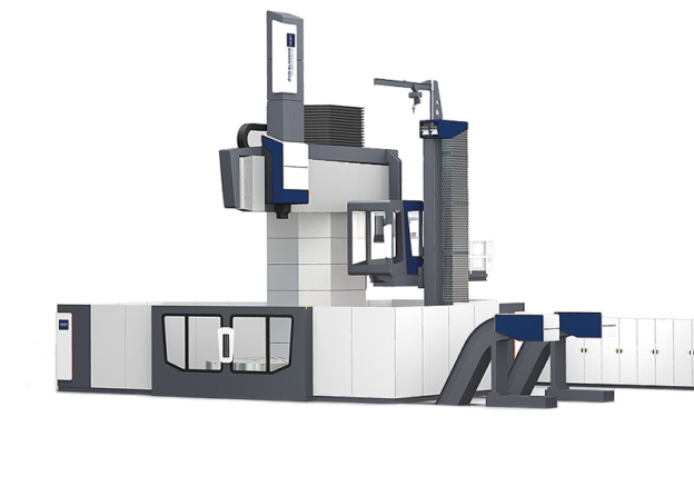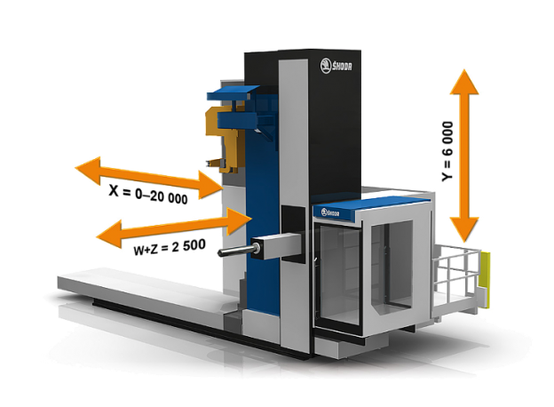
Horizontal milling and boring machine FCW

FCW 140, 150 and 160 – horizontal milling and boring machines, which are used in dusty working environments and when machining materials such as cast iron, special plastics or GFK.
Horizontal milling and boring machine FCW – Description of main groups of machine:
Bed
- Grey cast iron structure – GG 30 (DIN)
- Two guide ways
- Hardened guiding ribs for X travel. Part of compact linear guiding
- HEIDENHAIN linear scale for X-axis located on the bed
- Hardened teeth rack for X – axis feed bolted to the bed section
- Limit switches for X – axis
- Telescopic protective steel-sheet covers over the whole width of the bed
Saddle
- Grey cast iron structure – GG 30 (DIN)
- On bottom side of saddle there are 5 roller (linear) tanks on each guide way for X travel. Part of compact linear guiding
- Lubrication of tanks by means of grease
- Backlash-free twin-pinion gearbox driven by SIEMENS AC drive for movement in X – axis
- Hydraulically controlled clamping units in each corner of column saddle
Column
- Grey cast iron structure – GG 30 (DIN)
- Hardened guiding ribs for Y travel. Part of compact linear guiding
- Counterweight for ram’s dropping compensation inside the column; including chain pulleys for hanging of headstock
- HEIDENHAIN linear scale for Y-axis located on the column
- Ball screw with rotating nut for movement in Y – axis
- Limit switches for Y – axis
- Telescopic protective steel-sheet covers over and below the headstock
Headstock
- Grey cast iron structure – GG 25 (DIN)
- On backside of headstock there are 2 roller (linear) tanks on each guide way for Y travel. Part of compact linear guiding
- Lubrication of tanks by means of grease
- Consists of basic parts like ram, boring & milling spindle, frames, gearing etc.
- Gearbox for Y – axis movement driven by SIEMENS AC drive mounted on headstock
- Three-step spindle drive with gears in continuous mesh and hydraulically shifted claw clutches
- Thermal stabilization of oil fillings of the headstock and main drive gearbox
- Disc brake of main drive is hydraulically released
Ram
- Special cast iron GGG 60 (DIN)
- Ram’s movement via ball screw and AC feed drive SIEMENS
- Milling and boring spindle seated inside the ram
- Compact roller guiding for ram’s out travel
- Automatic clamping system of attachments onto ram’s face
- Automatic ram’s dropping compensation system
Ram’s dropping compensation system
- FCW machines use special SKODA automatic ram compensation system
- Ram out-travel is compensated by hydraulic cylinder, which is attached on the front chain of the headstock by means is connected with counterweight.
- Additional ram compensation system is working on a basis of supporting of ram from bottom by means of hydraulic cylinder.
- Pressures in hydraulic cylinders for both compensation sub-systems are controlled by CNC system of the machine.
- Automatic ram compensation is functional along whole out-travel of ram as well as when special milling and boring attachment loaded on the ram.
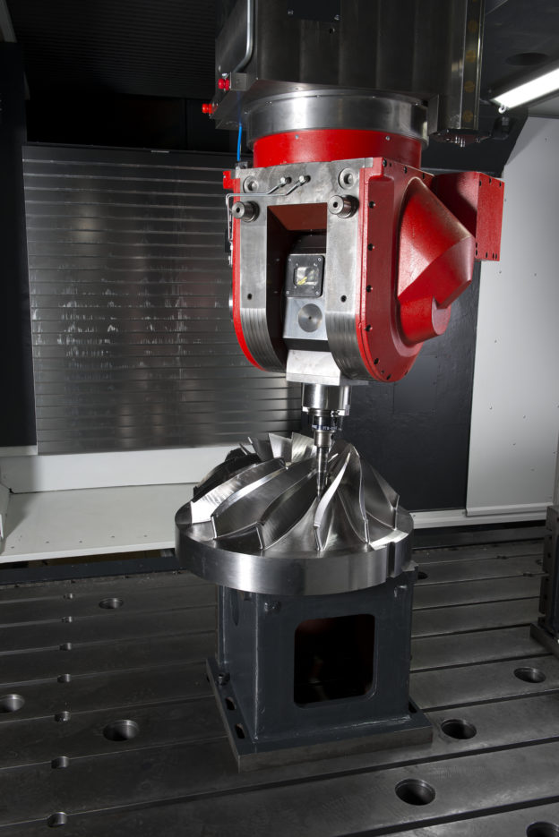
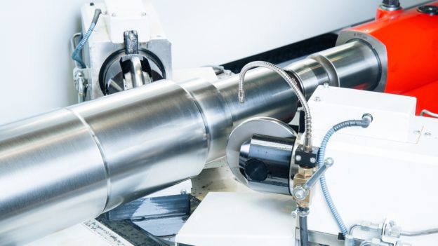
Boring spindle
- Special nitrided forging alloy steel, hardness HV 850
- Seated in milling spindle and ram. Seating of spindle in special ball bearings with oblique contact (maker SKF / FAG). Lubrication by means of oil mist
- Spindle’s movement via ball screw and AC feed drive SIEMENS
- Complete spindles’ seating dynamically balanced
- Oriented stop of spindle, spindle’s rotary encoder
- Mechanised tool clamping chuck collet as per DIN 69872 (hydraulically operated tool release, tool clamping by disk springs)
Operator’s platform and machine control
- Semi-closed operator’s platform firmly bolted to the column saddle. In front part and from above is protected against flying chips and splashing coolant based on international safety standards.
- Front part of the platform is moveable in ram’s direction (Z1) for 1 000 mm
- Main operator’s panel located on rotary pillar on the operator’s platform.
- Auxiliary portable panel with a cable with appr. 6 meters long for set-up and test purpose incl. position read-out
Hydraulic system and equipment
- Circuit for lubrication of spindle’s seating
- Circuit for thermal stabilisation of headstock and feed boxes with compressed cooler of used oil
- Circuit for thermal stabilisation of ram by means of controlled heating
- High-pressure circuit for auxiliary functions of machine like tool releasing, ram compensation, clamping units (X, Y), gear shifting, main disk brake, etc.
- High pressure air distribution for tool hollow’s cleaning, spindle seating sealing, sealing of scales of measuring system, etc.
Standard accessories
- Set of tools for maintenance (according to list in Operation manual)
- Set of spare parts for 2 years trouble free run of machine (according to list in Operation manual)
- 5 pieces of retention studs for clamping tools with tool taper ISO 50 (DIN 69871 – AD)
- Checking fixture EMA
- Anchoring material ŠKODA for machine (delivered without auxiliary materials for fixing like cement, grouting material etc.)