Request
FCW 140, FCW 150, FCW 160
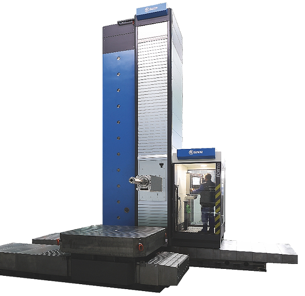
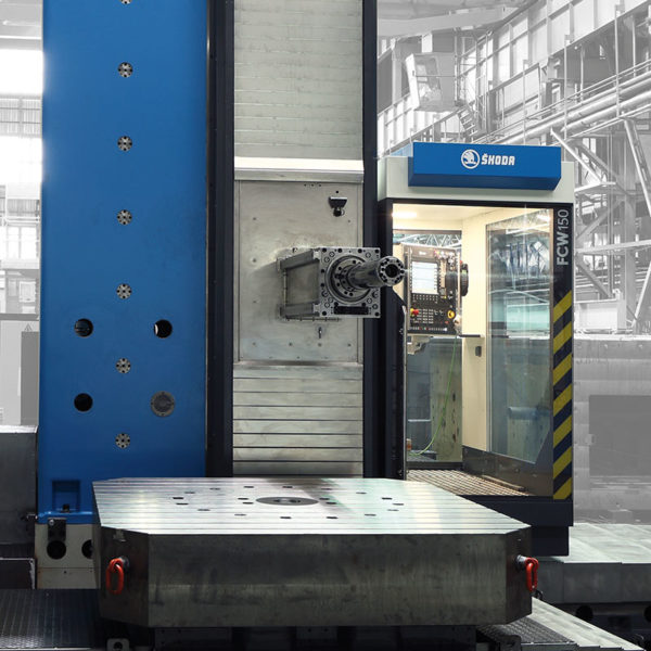

FCW 140, 150 and 160 - horizontal boring machines, which are used in dusty working environments and when machining materials such as cast iron, special plastics or GFK.
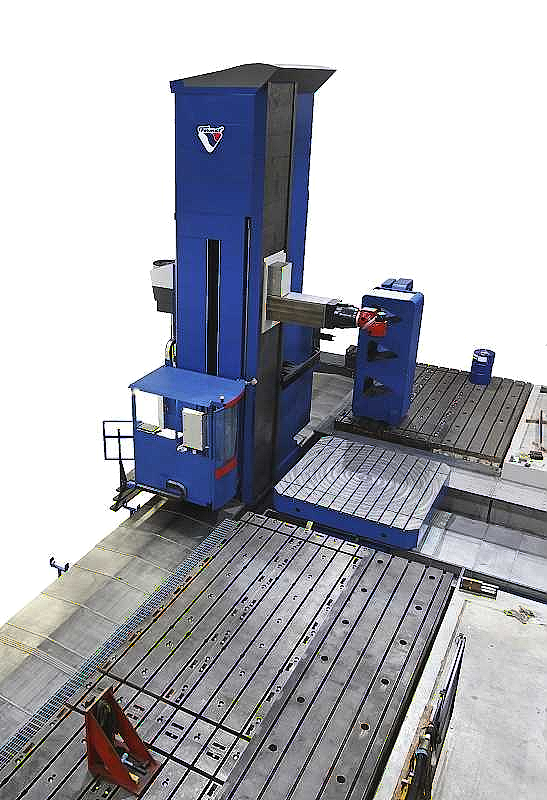
Horizontal milling and boring machine FCW
FCW 140, 150 and 160 – horizontal milling and boring machines, which are used in dusty working environments and when machining materials such as cast iron, special plastics or GFK.
Horizontal milling and boring machine FCW – Description of main groups of machine:
Bed
- Grey cast iron structure – GG 30 (DIN)
- Two guide ways
- Hardened guiding ribs for X travel. Part of compact linear guiding
- HEIDENHAIN linear scale for X-axis located on the bed
- Hardened teeth rack for X – axis feed bolted to the bed section
- Limit switches for X – axis
- Telescopic protective steel-sheet covers over the whole width of the bed
Saddle
- Grey cast iron structure – GG 30 (DIN)
- On bottom side of saddle there are 5 roller (linear) tanks on each guide way for X travel. Part of compact linear guiding
- Lubrication of tanks by means of grease
- Backlash-free twin-pinion gearbox driven by SIEMENS AC drive for movement in X – axis
- Hydraulically controlled clamping units in each corner of column saddle
Column
- Grey cast iron structure – GG 30 (DIN)
- Hardened guiding ribs for Y travel. Part of compact linear guiding
- Counterweight for ram’s dropping compensation inside the column; including chain pulleys for hanging of headstock
- HEIDENHAIN linear scale for Y-axis located on the column
- Ball screw with rotating nut for movement in Y – axis
- Limit switches for Y – axis
- Telescopic protective steel-sheet covers over and below the headstock
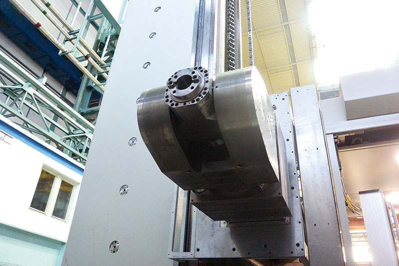
Headstock
- Grey cast iron structure – GG 25 (DIN)
- On backside of headstock there are 2 roller (linear) tanks on each guide way for Y travel. Part of compact linear guiding
- Lubrication of tanks by means of grease
- Consists of basic parts like ram, boring & milling spindle, frames, gearing etc.
- Gearbox for Y – axis movement driven by SIEMENS AC drive mounted on headstock
- Three-step spindle drive with gears in continuous mesh and hydraulically shifted claw clutches
- Thermal stabilization of oil fillings of the headstock and main drive gearbox
- Disc brake of main drive is hydraulically released
Ram
- Special cast iron GGG 60 (DIN)
- Ram’s movement via ball screw and AC feed drive SIEMENS
- Milling and boring spindle seated inside the ram
- Compact roller guiding for ram’s out travel
- Automatic clamping system of attachments onto ram’s face
- Automatic ram’s dropping compensation system
Ram’s dropping compensation system
- FCW machines use special SKODA automatic ram compensation system
- Ram out-travel is compensated by hydraulic cylinder, which is attached on the front chain of the headstock by means is connected with counterweight.
- Additional ram compensation system is working on a basis of supporting of ram from bottom by means of hydraulic cylinder.
- Pressures in hydraulic cylinders for both compensation sub-systems are controlled by CNC system of the machine.
- Automatic ram compensation is functional along whole out-travel of ram as well as when special milling and boring attachment loaded on the ram.
Boring spindle
- Special nitrided forging alloy steel, hardness HV 850
- Seated in milling spindle and ram. Seating of spindle in special ball bearings with oblique contact (maker SKF / FAG). Lubrication by means of oil mist
- Spindle’s movement via ball screw and AC feed drive SIEMENS
- Complete spindles’ seating dynamically balanced
- Oriented stop of spindle, spindle’s rotary encoder
- Mechanised tool clamping chuck collet as per DIN 69872 (hydraulically operated tool release, tool clamping by disk springs)
Operator’s platform and machine control
- Semi-closed operator’s platform firmly bolted to the column saddle. In front part and from above is protected against flying chips and splashing coolant based on international safety standards.
- Front part of the platform is moveable in ram’s direction (Z1) for 1 000 mm
- Main operator’s panel located on rotary pillar on the operator’s platform.
- Auxiliary portable panel with a cable with appr. 6 meters long for set-up and test purpose incl. position read-out
Hydraulic system and equipment
- Circuit for lubrication of spindle’s seating
- Circuit for thermal stabilisation of headstock and feed boxes with compressed cooler of used oil
- Circuit for thermal stabilisation of ram by means of controlled heating
- High-pressure circuit for auxiliary functions of machine like tool releasing, ram compensation, clamping units (X, Y), gear shifting, main disk brake, etc.
- High pressure air distribution for tool hollow’s cleaning, spindle seating sealing, sealing of scales of measuring system, etc.
Standard accessories
- Set of tools for maintenance (according to list in Operation manual)
- Set of spare parts for 2 years trouble free run of machine (according to list in Operation manual)
- 5 pieces of retention studs for clamping tools with tool taper ISO 50 (DIN 69871 – AD)
- Checking fixture EMA
- Anchoring material ŠKODA for machine (delivered without auxiliary materials for fixing like cement, grouting material etc.)
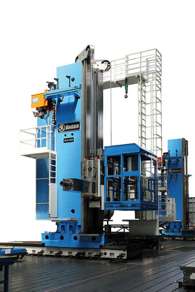
HCW1, HCW2, HCW3, HCW4
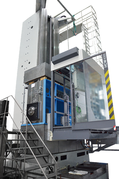
HCW 2000, HCW 3000, HCW 4000
FCW 140, FCW 150, FCW 160
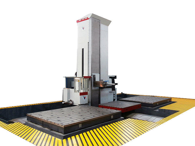
WRF 160 CNC / WRF 160 HEAVY
WRF150 CNC
WRF 130 CNC
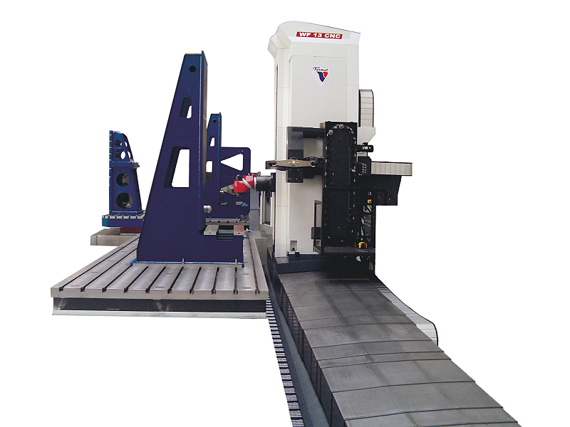
WF 13 CNC
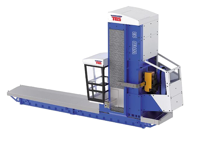
WRD 13 (Q)
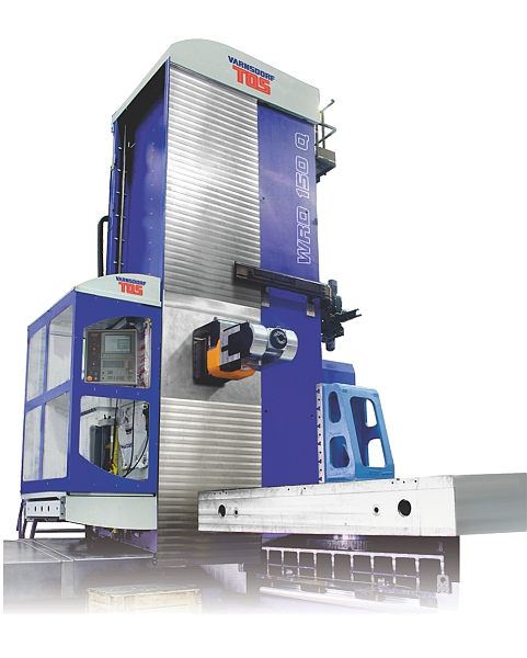
WRD 130 / WRD 150 (Q)
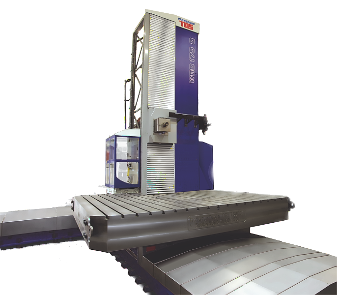
WRD 170 (Q)
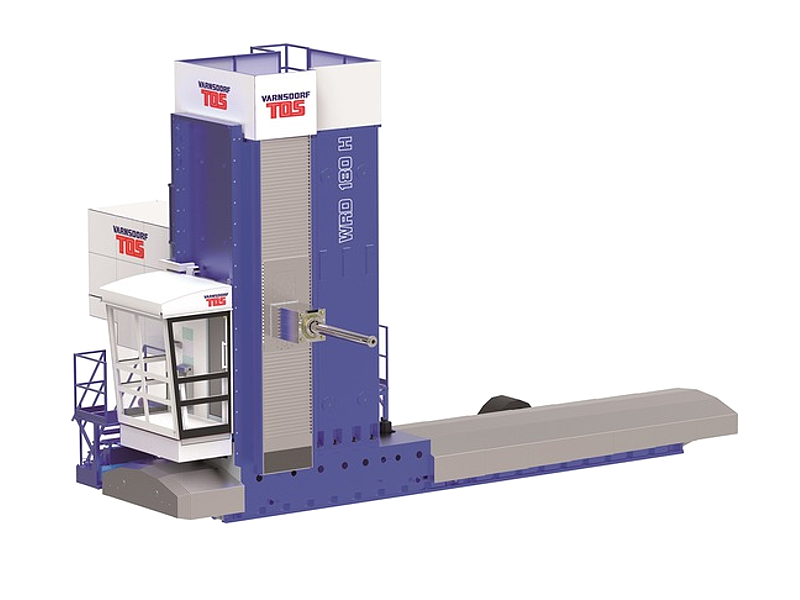
WRD 180 H
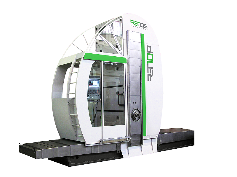
RET10P
https://www.youtube.com/watch?v=MztQ27SP-EI