Request
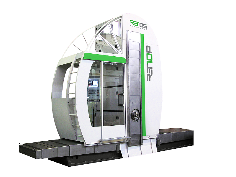
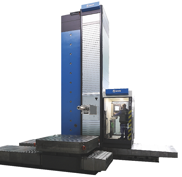
WRF150 CNC
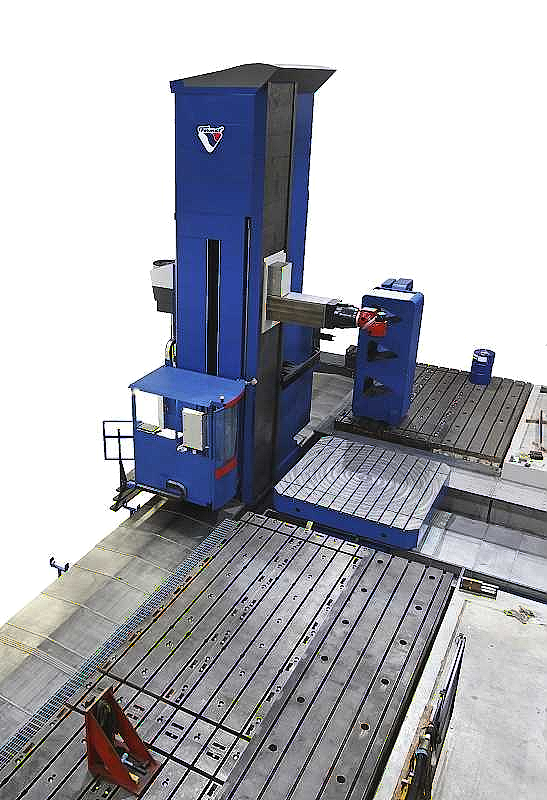
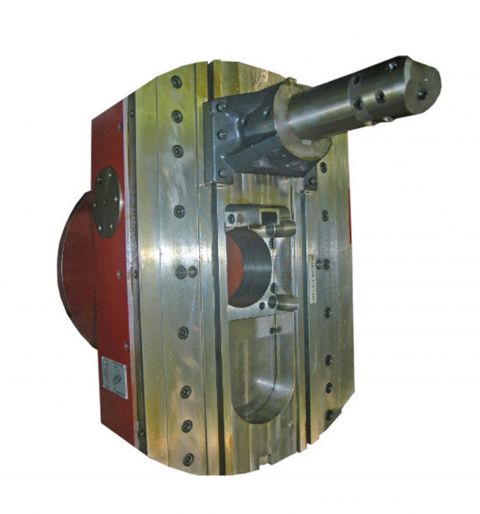
Floor type horizontal boring mill WRF 150 CNC represents the newest technology and concept of floor-type horizontal boring mills that are currently on the global marketplace. Its powerful headstock consists of a movable slide ram (Z-axis) and a moveable live spindle (W-axis).
Horizontal boring mill WRF150 CNC
Floor type horizontal boring mill WRF150 is a continuously controlled milling and boring machine with a travelling ram and a work spindle, with a longitudinally movable column base with the possibility of an optional table movable in a crosswise manner. WRF machines are very precise and thanks to their modern construction, they are very convenient for efficient machining of workpieces of up to 80 Tons on the optional rotary table, or higher on floor plates.
A consistent control of the machine is provided by a CNC system according to the customer’s choice (HEIDENHAIN iTNC 530, SIEMENS 840D SL or FANUC 31i B) with an English dialogue. A standard is the control of linear axes X, Y, Z, W, rotary axes of the work spindle (S). It is possible to additionally equip the machine, as standard accessories, with a rotary table (rotary axis B and linear axis V). The control panel on a rotary bracket is equipped with a color 15’’ screen. Standard equipment includes a portable control console – a hand wheel (type according to the CNC system, including a possibility of wireless transmission).
Basic parts of floor type horizontal boring mill WRF150: the longitudinal and alternatively cross-wise beds are made of cast iron GG30. The column base travel is up to 4 300 mm on the X axis and it is enabled through linear guides by a servomotor through a ball screw. For the travels from 4 900 mm, the column base travel on the X axis provided on the linear guides by two servomotors with pinions with the Master-Slave function to eliminate backlash on rack Gudel. The torque transfer from the servomotors to the pinions is through planetary gearboxes.
The column base and slides of the machine are constructed as thermally stabilized weldments. The column base moves on linear rolling guides. The linear guides and three ball screws on the column base enables the headstock travel on the Y axis. The inside of the column base is reinforced with stiffeners for higher rigidity. After the welding process and rough machining, the weldments are annealed in order to relieve inner stress, which contributes to the stability of the column base.
FRM Upínací úhelníky
FRM Upínací desky

FRM Pick Up
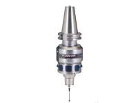
FRM Obrobkové a nástrojové měřící sondy
FRM Lícní desky
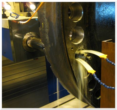
FRM Chlazení
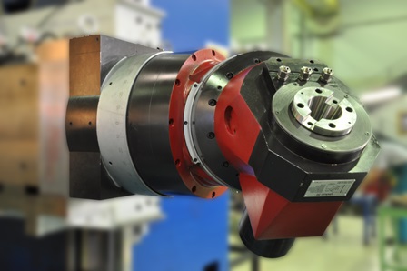
FRM Frézovací hlavy
FRM ATC
FRM APC
HCW1, HCW2, HCW3, HCW4
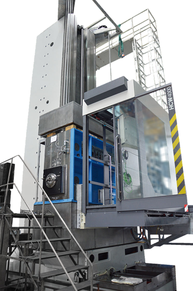
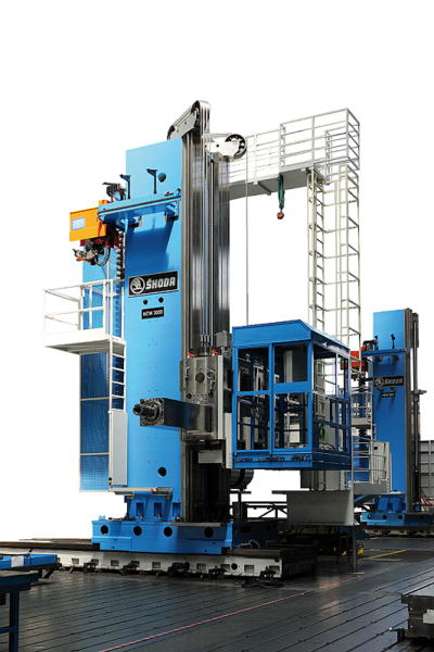
HCW 2000, HCW 3000, HCW 4000
FCW 140, FCW 150, FCW 160
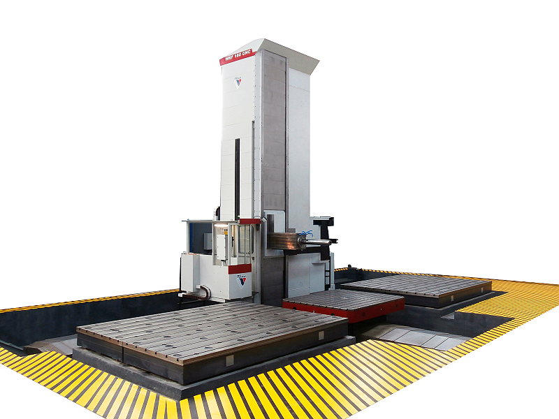
WRF 160 CNC / WRF 160 HEAVY
WRF150 CNC
WRF 130 CNC
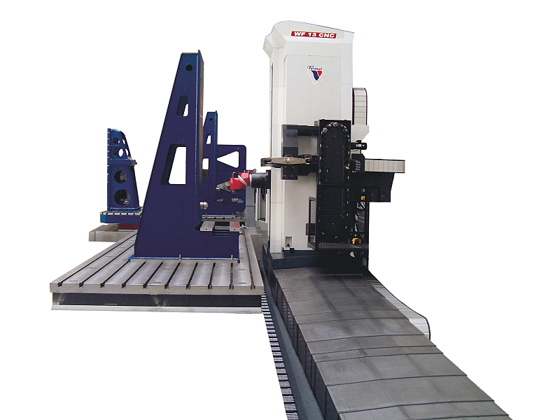
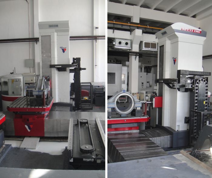
WF 13 CNC
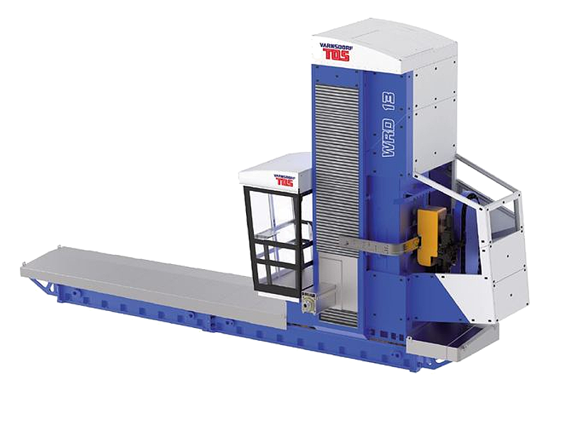
WRD 13 (Q)
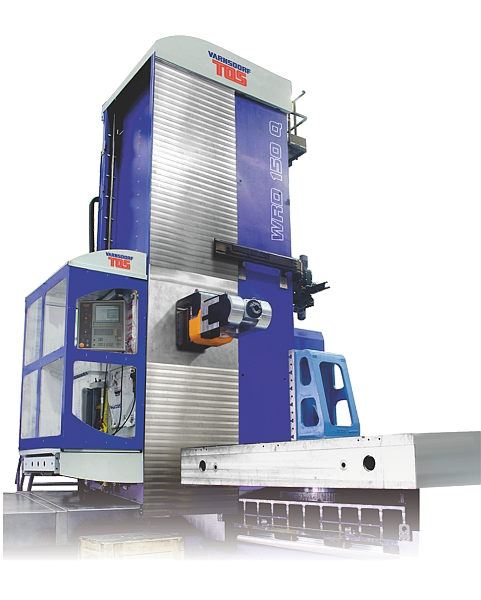
WRD 130 / WRD 150 (Q)
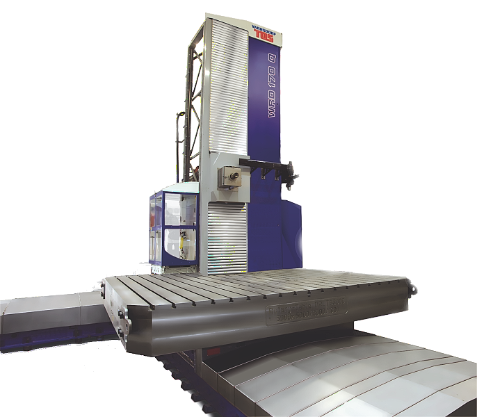
WRD 170 (Q)
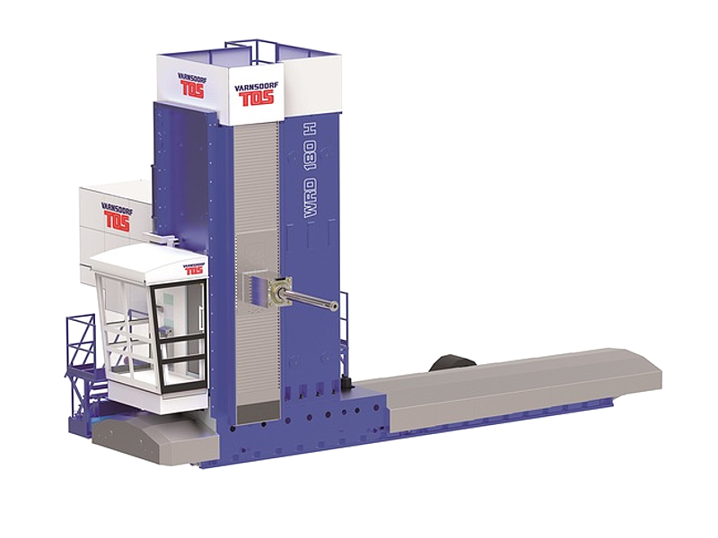
WRD 180 H